Intro
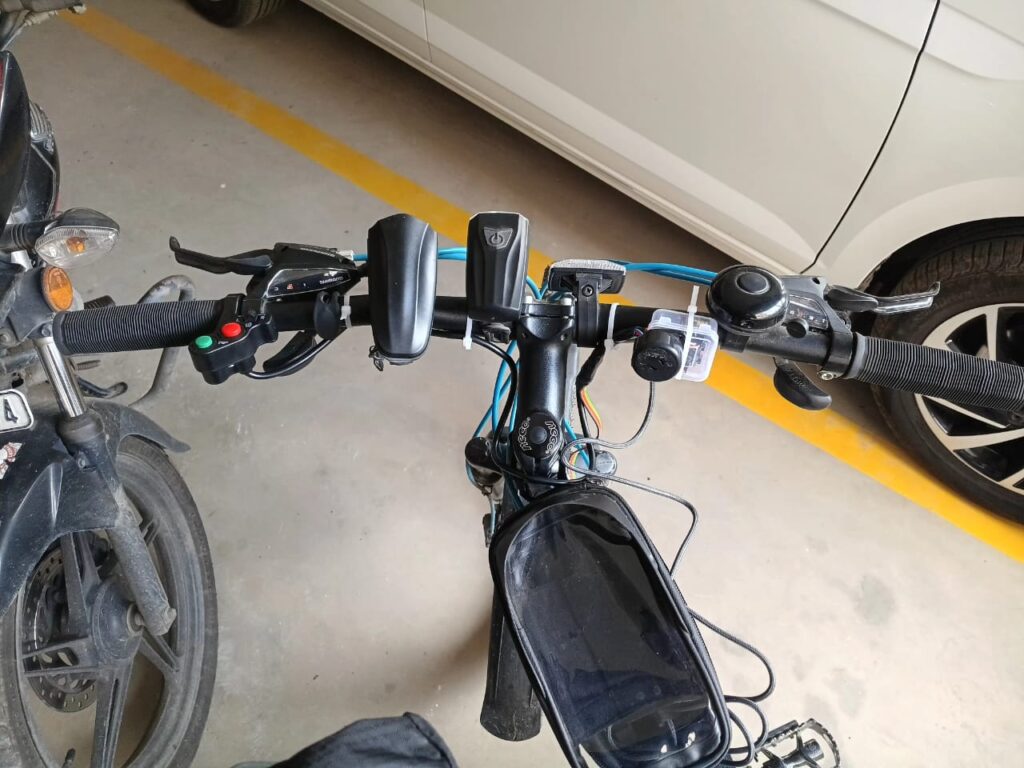
Ever since I started cycling with my Firefox Combat 27.5, I’ve wanted to make it a little smarter. Instead of a traditional bell, I wanted proper indicators, a horn, and maybe someday — GPS tracking and Home Assistant automation!
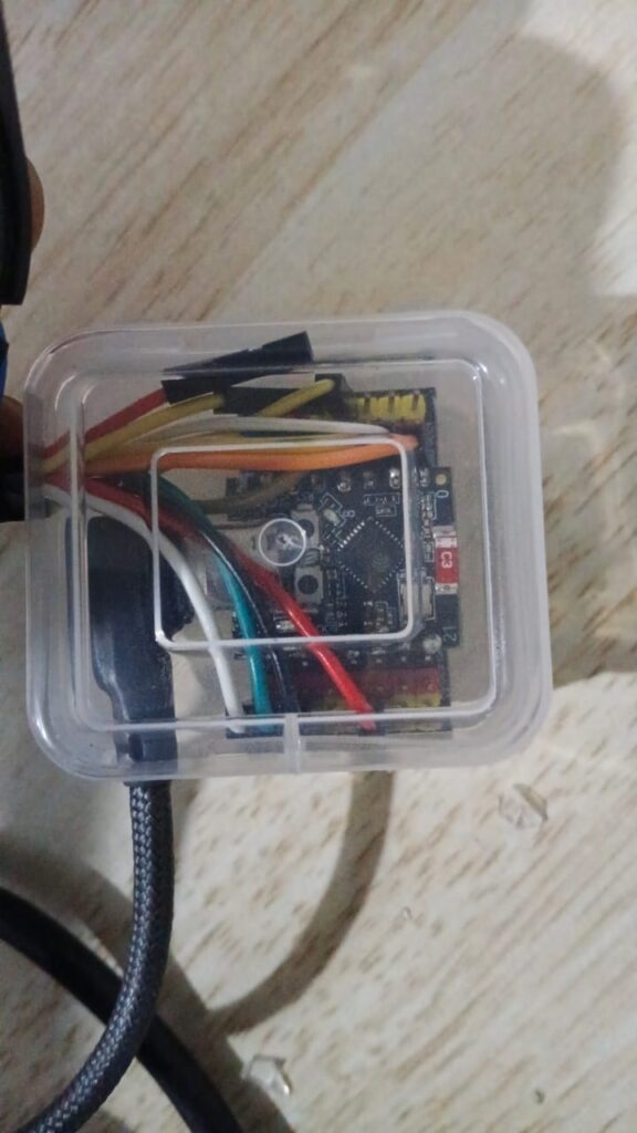
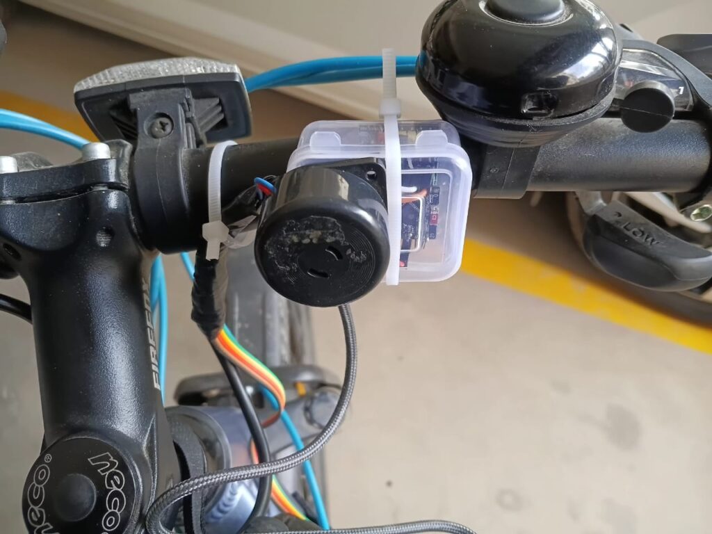
So, I began experimenting with an ESP32-C3 board to create a semi-DIY electronic control system for my bike — simple, reliable, and smart-home ready..
Components Used
| Component | Description | Link |
|---|---|---|
| ESP32-C3 Board | The main microcontroller, Wi-Fi + BLE, perfect for ESPHome | Robu.in – ESP32-C3 |
| Reflector Indicator Light | Rear reflector with built-in LED for left/right turn signal | Amazon Link |
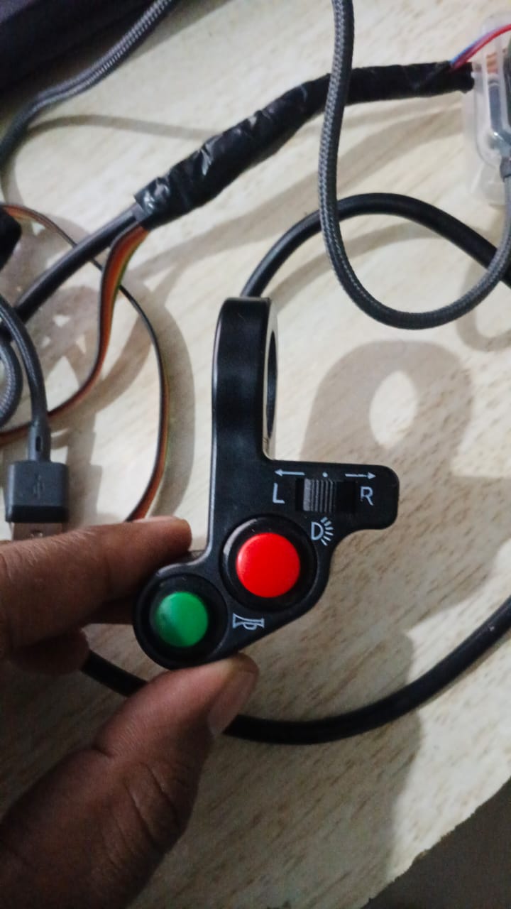
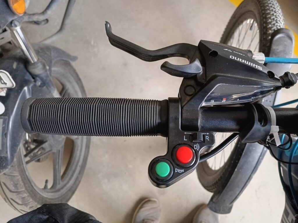
| Horn/Light ON-OFF Switch | Handlebar switch to trigger horn & indicators | Amazon Link |
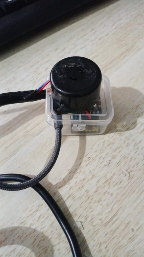
| Buzzer | Light Buzzing sound for indicator | Robu.in – Buzzer |
| LED Bulbs | Red LED Bulbs | Robu.in – LED |
| Electronic Horn (Future Integration) | 120 Decibel(Db) Horn | Firefox Bike Accessories – Horn |
Wiring & Setup
- The ESP32-C3 handles three main inputs from the switch:
- Left indicator
- Right indicator
- Horn (or buzzer)
- The outputs drive LED reflectors or a buzzer module.
- All powered via a small 5V battery pack (e.g., Mi power bank).
ESPHome YAML Config
esphome:
  name: esp32-c3-mini-bicycle
  friendly_name: esp32-C3-mini-bicycle

esp32:
  board: esp32-c3-devkitm-1
  framework:
    type: esp-idf

# Enable logging
logger:

# Enable Home Assistant API
api:
  encryption:
    key: "XXXXXXXXXXXXXXXXXXXXXXXXXXXXXXX"

ota:
  - platform: esphome
    password: "XXXXXXXXXXXXXXXXXXXXXXXXXXXXXXX"

  # Enable fallback hotspot (captive portal) in case wifi connection fails

captive_portal:

wifi:
  networks:
    - ssid: !secret wifi_ssid_vlan40
      password: !secret wifi_password_vlan40
    - ssid: !secret wifi_ssid_M06-006
      password: !secret wifi_password_M06-006
  ap:
    ssid: "Esp32-C3-Mini-Test"
    password: "XXXXXXXXXXXXXXXXXXXXXXXXXXXXXXX"

# ----------------------------
# 🟢 INPUTS (Switches)
# ----------------------------
binary_sensor:
  - platform: gpio
    pin:
      number: GPIO3    # Left button (instead of GPIO2)
      mode: INPUT_PULLUP
      inverted: true
    id: left_switch
    name: "Left Switch"
    filters:
      - delayed_on: 10ms
      - delayed_off: 10ms

  - platform: gpio
    pin:
      number: GPIO5    # Right button (instead of GPIO3)
      mode: INPUT_PULLUP
      inverted: true
    id: right_switch
    name: "Right Switch"
    filters:
      - delayed_on: 10ms
      - delayed_off: 10ms


# ----------------------------
#  OUTPUTS (LEDs + Buzzer)
# ----------------------------
output:
  - platform: gpio
    pin: GPIO6
    id: left_led

  - platform: gpio
    pin: GPIO7
    id: right_led

  - platform: gpio
    pin: GPIO10
    id: buzzer_output

# ----------------------------
#  LIGHT ENTITIES
# ----------------------------
light:
  - platform: binary
    name: "Left Indicator"
    output: left_led
    id: left_indicator

  - platform: binary
    name: "Right Indicator"
    output: right_led
    id: right_indicator

# ----------------------------
#  BUZZER SWITCH
# ----------------------------
switch:
  - platform: output
    name: "Indicator Buzzer"
    output: buzzer_output
    id: indicator_buzzer

# ----------------------------
# 🔁 AUTOMATION: Blink Logic
# ----------------------------
interval:
  - interval: 500ms
    then:
      # Left Indicator
      - if:
          condition:
            binary_sensor.is_on: left_switch
          then:
            - light.toggle: left_indicator
            - switch.toggle: indicator_buzzer
          else:
            - light.turn_off: left_indicator

      # Right Indicator
      - if:
          condition:
            binary_sensor.is_on: right_switch
          then:
            - light.toggle: right_indicator
            - switch.toggle: indicator_buzzer
          else:
            - light.turn_off: right_indicator

      # Turn off buzzer when neither switch is pressed
      - if:
          condition:
            and:
              - binary_sensor.is_off: left_switch
              - binary_sensor.is_off: right_switch
          then:
            - switch.turn_off: indicator_buzzer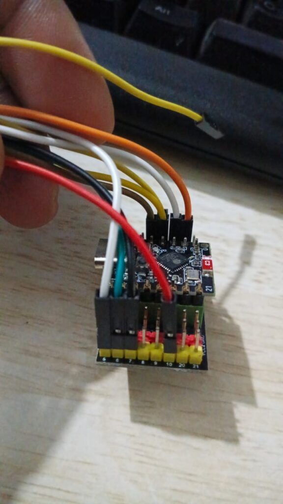


Future Scope
- Integrate headlight and horn directly into the ESP32-C3 logic
- Add GPS module (e.g., NEO-6M) for live tracking
- Use Bluetooth Low Energy for smartphone integration
- Log ride stats or location to Home Assistant / Grafana
- Remotely Send telemetry via MQTT or Other methods to Home Assistant.
Closing Thoughts
This small project made my rides more fun — and safer! Having turn indicators and a horn connected through ESPHome gives me full control and opens up endless automation possibilities.
Stay tuned — next, I’ll integrate GPS and lighting automation into the same system. 🚴♂️💡
[…] I already have a DIY Cycling Indicator + Horn system running on an ESP32-C3 (from my previous project), the next step is to bring this GPS data into the […]